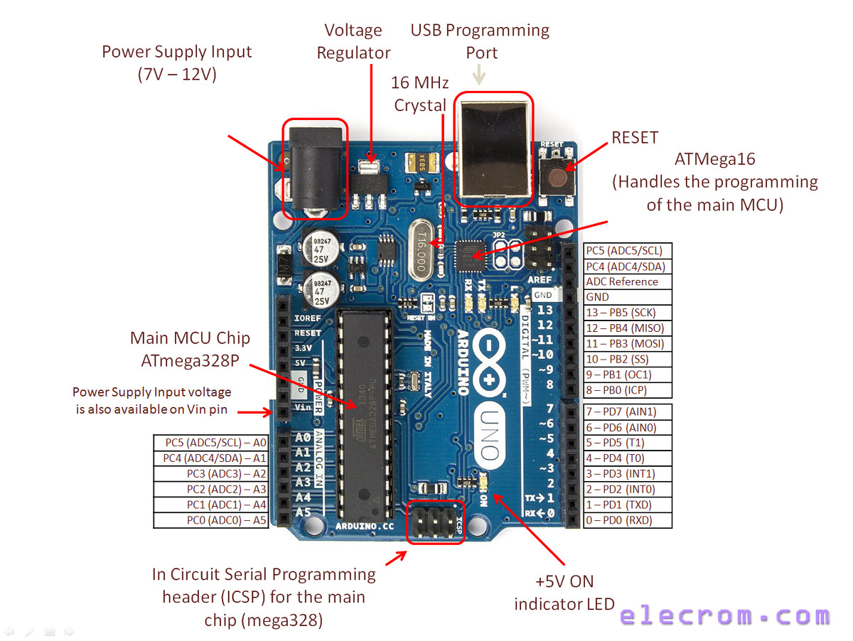

Hence suggestion 2) that not all the code in the command braces is being run properly.Īlso, if I remove the element in the first while cycle condition which limits the number of times that the cycle runs to 10, then it seems to just get stuck in an infinite loop. If that conditional is met, then the word "high" should also be printed across the serial, which is it not being. This is odd because once the LED is dimmed, it should not be brightened again unless the conditional inside the first cycle is met - which requires digitalRead() to have read HIGH. What actually happens is that the LED dims and brightens every 2 seconds, but only the word "low" ever gets printed across the serial. It should start with a brightly lit LED, then print "high", then dim the LED and print "low", then brighten the LED and print "high" - and so on. There is a 2 second delay between each cycle, in order to see the change. The second cycle repeats until digitalRead() reads the state of the PWM pin to be LOW, and then makes the LED dim and prints the word "low" over serial. The first cycle repeats until digitalRead() reads the state of the PWM pin to be HIGH, and then makes the LED bright and prints the word "high" over serial. In the loop there are two separate cycles: In the setup the digital pin 11 is set to PWM with a value of 70. I reduced the code down to a test problem, based on the LED fade default sketch example.Īn LED is connected between digital pin 11 and ground. (This problem is related to a question I asked in the sensor forum ). It seems to always read either HIGH or always LOW.

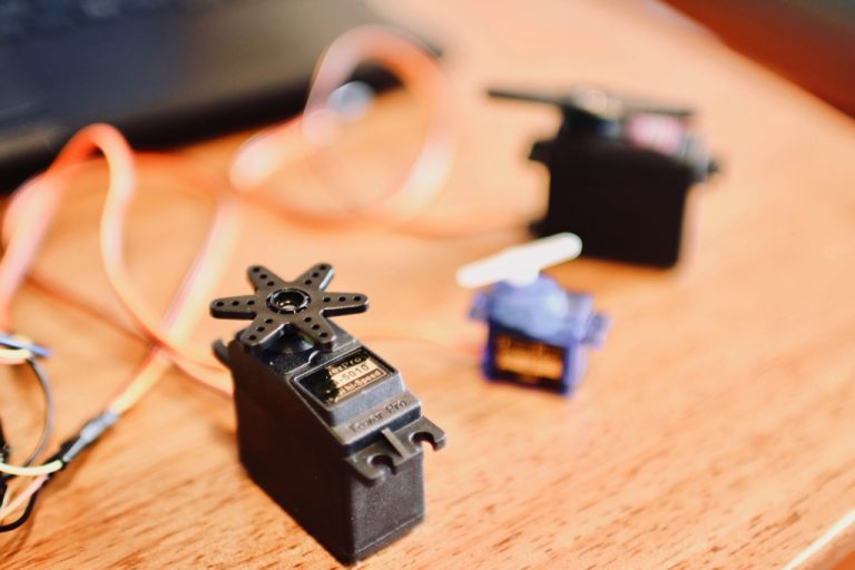
Sketch_nov12c:20: error: request for member 'attach' in 'servo', which is of non-class type 'VarSpeedServo ' While (digitalRead(10) = 0) //blink led 13 until setup switch is openedĪrduino: 1.8.4 (Windows 7), Board: "Arduino/Genuino Mega or Mega 2560, ATmega2560 (Mega 2560)"Ĭ:\Users\bob\Documents\Arduino\Sketches\sketch_nov12c\sketch_nov12c.ino: In function 'void setup()': blink on board LED 13 to indicate Center Mode of operation test if switch on input 10 is closed to ground and if so center all servos slowmove (closepos,20) // second arg is servo speed, 20 is about 3 seconds slowmove (openpos,20) // second arg is servo speed, 20 is about 3 seconds

If (digitalRead(portNumber ) = 0) //read all inputs and outputs servo.move commands reads input conditions and moves servos if required If (digitalRead(10) = 0) centerAll() //looks for a low on pin 10, provided by a SPST switch to GND

PinMode(10, INPUT) //set up input pin for centering mode switchĭigitalWrite(10, HIGH) //pull up resitor set for center mode switch PinMode (portNumber, INPUT) //set up input pins attach(servoPin ) // attach servos to output pins Int mid = 90 //value (in degrees) for servo mid postion Int openpos = 60 //value (in degrees) for servo open postion Int closepos = 120 //value (in degrees) for servo closed position value Int pins = //intialize output pins servos connect to MRH 6 Switched 6 Servos with Pushbuttons & LED Indicators


 0 kommentar(er)
